Home > Articles > Access Serial Ports with PICBASIC
Access Serial Ports with PICBASIC
This article originally appeared in the May 2008 Nuts & Volts.
Also see Access Serial Ports with Visual Basic .NET.
Last time I showed how to use Visual Basic .NET to transfer data via a PC’s serial ports, including USB virtual COM ports. I described a Visual Basic application that sends commands and receives responses from a device connected via a serial port.
This month I’ll show a companion PICBASIC PRO program for a PIC microcontroller. The program detects received commands, takes requested actions, and sends responses. I’ll also show how to use an RS-422 interface to create serial links as long as 4000 ft.
Serial Port Hardware
I wrote the code in this article for a PIC18F4520 microcontroller. Like many PICs, the PIC18F4520 has a built-in serial port. The chip’s EUSART manages serial communications and supports an asynchronous mode that is compatible with serial ports on PCs. PORTC.6 (TX) is the serial output, and PORTC.7 (RX) is the serial input.
I ran the code on Microchip’s PICDEM 2 Plus development board. On the board, the PIC’s serial port interfaces to a MAX3232 chip, which converts between the PIC’s 5V signals and RS-232 voltages. The board has a 9-pin female D-sub connector for the RS-232 cable.
Most RS-232 serial ports on PCs have male 9-pin D-subs. USB/RS-232 adapters are also available with these connectors. To connect a PICDEM 2 Plus board to a serial port on a PC, use a straight-across cable, not a null-modem cable or adapter, which swaps the lines in the cable. If in doubt, use an ohmmeter. With a probe on pin 2 of each connector on the cable, the resistance should measure close to zero.
Why use a serial port and not USB? Serial ports are a good choice when you want to keep things simple and inexpensive. The program code to access a serial port is less complex than what’s required to communicate via USB. Plus, the number of microcontrollers with embedded serial ports is much greater than those with embedded USB controllers.
Accessing the Port
Listing 1 is PICBASIC code that configures the PIC’s serial port and runs the main program loop. (The complete code plus a Visual Basic .NET project to use with it are available from www.nutsvolts.com and my website, janaxelson.com.)
In the PIC, several registers enable the port, set the bit rate, and store received data and data to transmit. The chip’s data sheet details the functions of the register bits.
The example program contains an endless do-nothing loop. A real-world application can perform any needed actions in the loop. For example, a monitoring device can read sensor data, or a motor-control device can send control signals to the motors.
Listing 2 is an interrupt service routine (ISR) for the serial-port’s receive interrupt. The ISR runs when a new byte has arrived at the serial port. On a framing error, the routine reads the data to clear the error but otherwise ignores the data. Causes for framing errors include bit rates that don’t match and a noisy line.
On receiving data without an error, an hserin statement stores incoming data until receiving a line-feed (LF) code of 0Ah, receiving 5 bytes, or waiting 1 second, whichever occurs first.
On a timeout, the ISR exits with no further action. On receiving a LF or five bytes, the ISR calls the routine in Listing 3. The routine checks to see if the serial port received a valid command.
The routine understands two commands, “L11” and “L10”. On receiving “L11”, the routine sets PORTB.0 = 1 to turn on LED RB1 on the PICDEM 2 Plus board. The device then sends an acknowledgment consisting of the character “1” followed by a LF. On receiving “L10”, the routine sets PORTB.1 = 1 to turn off LED RB1 and sends the character “0” followed by a LF.
A remote computer that sends a command and receives either “0” or “1” followed by a LF can assume the command was received and carried out.
You can test this code with the Visual Basic .NET example presented last time, or you can type commands and view responses in a terminal-emulator utility such as Hyperterminal. Some terminal emulators send a carriage-return (CR) code (0Dh) preceding the LF at the end of each line. The PICBASIC code ignores a received CR before the LF.
Preventing Overflows
On the PIC18F4520, the serial port’s input buffer can hold just two received bytes. If the buffer is full and a third byte arrives before program code has retrieved at least one of the bytes from the buffer, the new byte has nowhere to go and is dropped.
Using an ISR helps the program respond quickly to received data. When a byte arrives at the serial port, the code in the ISR runs as soon as the currently executing PICBASIC statement completes.
In the ISR, the hserin statement waits to receive all of the bytes in a command, storing the bytes as they arrive. Waiting for the entire command prevents buffer overflows. The penalty is that the code can’t do anything else while waiting for the rest of the command to arrive.
Because the currently executing statement must finish before the ISR runs, avoid statements that take a long time to execute, such as pauses with long delays. If you need faster response, PICBASIC supports using ISRs written in assembly code. Another way to allow more time to retrieve received data is to use a slower bit rate, which results in more time between received bytes.
Some systems use hardware flow control, also called handshaking, to prevent missed data. RS-232 has defined hardware flow-control signals. On a PC’s port, Request to Send (RTS) is an output, and Clear to Send (CTS) is an input.
On a PIC, hardware flow control requires two otherwise unused port bits and an additional RS-232 driver and receiver. The MAX3232 on the PICDEM2 Plus board has a spare driver and receiver.
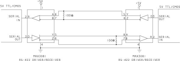
Figure 1. A MAX3232 converts between 5V logic and RS-232 voltages.
You can solder jumper-wire connections to these (Figure 1), but the chip is surface mount, so soldering can be tricky. Another option is to solder another MAX3232 or similar interface chip in a through-hole package to the board’s prototyping area and wire the needed connections to the chip.
In Figure 1, note that the RS-232 signals are named from the perspective of the remote PC. The PIC’s TX output controls RS-232’s RX signal, which is an input on the PC, and RS-232’s TX signal, which is an output on the PC, controls the PIC’s RX input.
Some development boards wire CTS and RTS together at the RS-232 connector. If you need to use hardware flow control, check your board’s schematic and cut any unwanted connections.
In a PIC using hardware flow control, program code must bring the CTS port bit high when the port isn’t ready to receive data. The RS-232 driver inverts the signal, so on the cable, CTS is a negative voltage. At a PC that wants to send data to the PIC, an RS-232 interface chip re-inverts CTS, resulting in a logic high output. The PC must detect the state of CTS and stop sending data when the output is logic high.
When sending data using hardware flow control, program code must detect the state of RTS and send data only when RTS is logic low at the PIC (and thus a positive voltage on the RS-232 cable). PC software uses large buffers, so when communicating with a PC, the PIC isn’t likely to need to monitor RTS.
PICBASIC PRO and other PIC compilers can also create software serial ports using any spare port pins. Instead of using the chip’s hardware EUSART, the compiler controls communications with the help of an on-chip timer.
For software ports, PICBASIC’s serin2 statement can name a flow-control output bit that toggles automatically as needed to prevent overflows, and serout2 can name a flow-control input bit. Software ports can’t use the serial port’s hardware interrupt, however.
Two other RS-232 signals are DTR and DSR. Some PC software requires DSR to be asserted (positive RS-232 voltage) to signify the device is powered. The PICDEM 2 Plus board connects DTR to DSR on the RS-232 connector so at the remote computer, the DSR input always follows the DTR output.
To enable using DTR and DSR for flow control or other uses, cut the circuit-board trace that connects these signals together. Add an RS-232 driver and receiver and wire connections to spare port pins and the D-sub connector.
Setting the Bit Rate
A serial port’s bit rate is the number of bits per second the port transmits or receives. In basic data links, the bit rate equals the baud rate, and you can use either term as you prefer.
To set a PIC’s bit-rate clock, program code configures an on-chip timer with a period as close as possible to the width of one bit at the desired bit rate. For example, at 9600 bits per second (bps), each bit is 104 microsecs. wide. The CPU’s clock source (FOSC) and values in registers determine the timer’s period.
In the TXSTA register, the BRGH bit selects a multiplier to use in configuring the timer. In the BAUDCON register, the BRG16 bit determines whether an 8- or 16-bit value sets the timer’s period. The SPBRG register stores the value’s low 8 bits. For 16-bit values, the SPBRGH register stores the upper 8 bits. (Not all PICs support using 16-bit values.)
Often an exact match to the desired bit rate isn’t possible. The chip’s crystal or other timing source can also introduce error by varying slightly from its rated frequency. In general, the bit rates on both ends of the line can differ by up to about 3% without causing errors. Because you typically don’t know the accuracy of the other end’s clock, it makes sense to use settings that give the closest match possible.
A quick way to obtain values for a desired bit rate is to consult the tables in the chip’s data sheet. For the device’s FOSC value and desired bit rate, select the values that give the smallest error.
For example, for a PICDEM 2 Plus board with FOSC = 4 MHz and desired bit rate of 9600 bps, setting BRGH = 1 and BRG16 = 0 gives a close match with a bit rate of 9615 bps. With BRGH = 0 and BRG16 = 0, the best match is 8929 bps, an error of almost 7%.
PICBASIC’s hser_baud statement checks the value of BRGH, assumes BRG16 = 0, and sets SPBRG for the closest match to the requested bit rate. To use a 16-bit timer value, set BRG16 and load the SPBRG and SPBRGH registers directly instead of using hser_baud:
' Enable the transmitter and set BRGH = 1.
define HSER_TXSTA 24h
' Set BRG16 (BAUDCON.3) = 1.
baudcon = 8
' Load SPBRG and SPBRGH for the desired bit rate.

  ' (Use 19fh for 2400 bps.)
define hser_spbrgh = 1

  define hser_spbrg = 9fh
If your circuit’s FOSC value isn’t listed in the tables, the data sheet provides formulas for selecting values.
Extending a Link with RS-422
RS-232 is a rugged interface suitable for cables of up to around 100 ft using off-the-shelf, unshielded cables. The exact limit varies with the cable’s capacitance. To help prevent data errors, the interface uses wide voltage swings and limits the slew rate, or rate of change, at the outputs.
If you need a cable of up to 4000 ft, RS-422 is an option. Program code that communicates via an RS-232 port can also communicate via RS-422 with no changes.
RS-422 uses balanced lines, where each signal has a dedicated pair of wires. The voltage on one wire equals the complement of the voltage on the other wire. The receiver detects the voltage difference between the lines. Balanced lines are electrically quiet because most noise is common to both wires and thus cancels out.
For best performance with RS-422, use twisted-pair cable. Each pair is two insulated wires that twist around each other every inch or so for the length of the cable. Connect each signal’s two lines to wires in the same pair.
The cable should have a characteristic impedance of 90 to 150 ohms. Characteristic impedance is a measure of the impedance of an infinite line. The value doesn’t change with the cable’s length. For RS-422, a good choice is network cable such as Category 5e cable, which has a characteristic impedance of 100 ohms.
Every RS-422 interface must have a ground line or other connection to carry the current that results from any mismatch between the drivers on a line.
Figure 2 shows an RS-422 interface to a microcontroller.
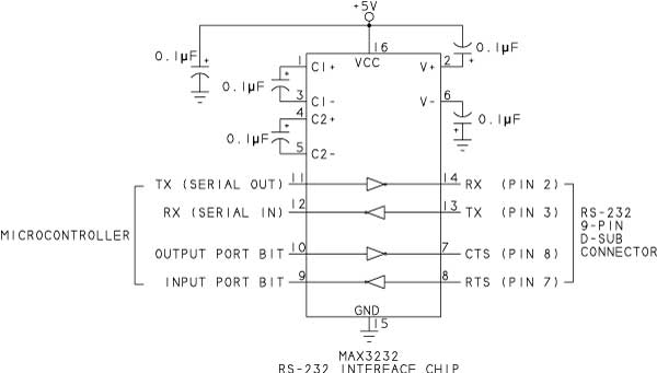
Figure 2. An RS-422 interface can use longer cables than RS-232.
The interface chip is a MAX3081. A 100-ohm resistor at each receiver provides a termination that absorbs voltage reflections when the outputs switch. The termination resistor should match the cable’s characteristic impedance.
Unlike other RS-422 chips, which can handle bit rates as fast as 10 Mbps, the MAX3081 has a limited slew rate that reduces the maximum bit rate to 115,200 bps. An advantage to the chip is that cables of 220 ft or less can eliminate the terminating resistors.
The cable can be as long as 4,000 ft at bit rates up to around 90 kbps. At 115,200 bps, the maximum cable length drops to around 3000 ft.
On a PC, a quick way to obtain an RS-422 port is to attach a USB/RS-422 adapter. An example is USBGear’s USB-COMi-M, available from Saelig Company. Other options are RS-422 expansion cards and RS-232/RS-422 converters.
To use hardware flow control with RS-422, add another MAX3081 or similar driver/receiver pair and a twisted pair for each. RS-485 is a similar interface that also supports serial networks that share a single data path. The MAX3081 is compatible with both RS-422 and RS-485.
Jan Axelson is the author of Serial Port Complete, now in its Second Edition. Jan’s website is janaxelson.com
Links
RS-232 and RS-485 interface chips
Maxim Integrated Products
PIC microcontrollers
Microchip Technology
PICBASIC PRO
microEngineering Labs, Inc.
USB-COMi-M USB/RS-422 converter
Saelig Company Inc.
Copyright Jan Axelson 2008-2009