Home > Articles > RS-485 Circuits for All Occasions
Designing RS-485 Circuits
Jan Axelson
This article was originally published in Circuit Cellar.
When a network needs to transfer small blocks of information over long distances, RS-485 is often the interface of choice. The network nodes can be PCs, microcontrollers, or any devices capable of asynchronous serial communications. Compared to Ethernet and other network interfaces, RS-485's hardware and protocol requirements are simpler and cheaper.
The RS-485 standard is flexible enough to allow a choice of drivers, receivers, and other components depending on the cable length, data rate, number of nodes, and the need to conserve power. Several vendors offer RS-485 transceivers with various combinations of features. In addition, there are options for methods of terminating and biasing the line and controlling the driver-enable inputs.
In this article, I show several circuits for RS-485 networks. Even if you use prebuilt cards or converters, understanding the options will help you choose the right product and configure it to get the best results for your application.
RS-485 in Brief
But first, a quick look at RS-485. The interface popularly known as RS-485 is an electrical specification for multipoint systems that use balanced lines. RS-485 is similar to RS-422, but RS-422 allows just one driver with multiple receivers, while RS-485 supports multiple drivers and receivers.
The specification document, TIA-485-A, defines the electrical characteristics of the line and its drivers and receivers. There are brief suggestions relating to terminations and wiring, but unlike RS-232, there's no discussion of connector pinouts or software protocols.
An RS-485 network can have as many as 32 unit loads, with one unit load equivalent to an input impedance of 12k. By using high-impedance receivers, you can have as many as 256 nodes.
An RS-485 link can extend as far as 4000 ft., and can transfer data at up to 10 Mbps, but not both at the same time. At 90 kbps the maximum cable length is 4000 ft; at 1Mbps, it drops to 400 ft, and at 10Mbps, to 50 ft. For more nodes or very long distances, you can use repeaters that regenerate the signals and begin a new RS-485 line.
Although the RS-485 standard says nothing about protocols, most RS-485 links use the familiar asynchronous protocols supported by the UARTs in PCs and other computers. A transmitted word consists of a Start bit followed by data bits, an optional parity bit, and a Stop bit.
Two ways to add RS-485 to a PC are on an expansion card and by attaching an RS-485 converter to an existing port. Converters for RS-232 and USB are available. On microcontrollers, you can connect an RS-485 transceiver to any asynchronous serial port.
Many network circuits also require a port bit to control each transceiver's driver-enable input. Ports designed for RS-232 communications can use the RTS output. If that's not available, any spare output bit will do.
Most serial-communications tools, including Visual Basic's MSComm, support RS-485 communications with RTS controlled in software. WCSC's COMM-DRV serial-port drivers have automatic RTS control built-in.
The main reason why RS-485 links can extend so far is their use of balanced, or differential, signals. Two wires, usually a twisted pair, carry the signal voltage and its inverse. The receiver detects the difference between the two. Because most noise that couples into the wires is common to both wires, it cancels out.
In contrast, interfaces like RS-232 use unbalanced, or single-ended, signals. The receiver detects the voltage difference between a signal voltage and a common ground. The ground wire tends to be noisy because it carries the return currents for all of the signals in the interface, along with whatever other noise has entered the wire from other sources. And noise on the ground wire can cause the receiver to misread transmitted logic levels.
The chips' data sheets label the non-inverted RS-485 line as line A, and the inverted line as line B. An RS-485 receiver must see a voltage difference of just 200mV between A and B. If A is at least 200mV greater than B, the receiver's output is a logic high. If B is at least 200mV greater than A, the output is a logic low. For differences less than 200mV, the output is undefined.
At the driver, the voltage difference must be at least 1.5V, so the interface tolerates a fair amount of non-common-mode noise and attenuation.
Vendors of RS-485 transceivers include Linear Technology, Maxim, National Semiconductor, and Texas Instruments. These companies are also excellent sources for application notes containing circuit examples and explanations of the theory behind them.
RS-485 is designed to be wired in a daisy-chain, or bus, topology. Any stubs that connect a node to the line should be as short as possible. Most links use twisted pairs because of their ability to cancel magnetically and electromagnetically coupled noise.
A General-purpose Network
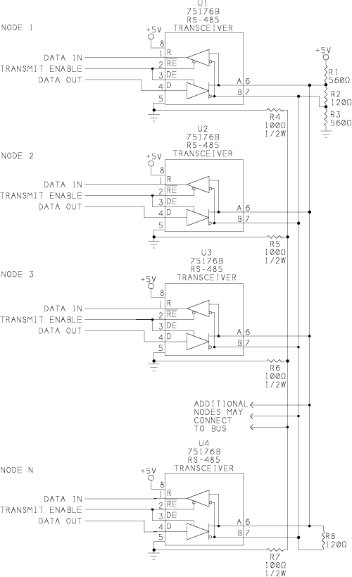
Here is a node for a general-purpose RS-485 network:

Each node has a Texas Instruments SN75176B transceiver that interfaces between RS-485 and TTL logic levels. The chip has a 2-wire RS-485 interface, a TTL driver input and receiver output, and TTL enable inputs for the driver and receiver. Similar chips include Linear Technology's LTC485, Maxim's MAX485, and National Semiconductor's DS3695.
The circuit has two 120-ohm terminating resistors connected in parallel, at or just beyond the final node at each end of the link. One end of the link also has two 560-ohm biasing resistors.
The terminations reduce voltage reflections that could cause the receiver to misread logic levels. The receiver sees reflected voltages as an output switches and the line settles from its initial current to its final current. The termination eliminates reflections by making the initial and final currents equal.
The initial current is a function of the line's characteristic impedance, which is the input impedance of an infinite, open line. The value varies with the wires' diameters, the spacing between them, and type of insulation.
For digital signals, which mainly consist of frequencies greater than 100 kHz, the characteristic impedance is mostly resistive; the inductive and capacitive components are small. A typical value for AWG #24 twisted pair is 120 ohms.
The final current is a function of the line termination, the receivers' input impedance, and the line's series impedance. In a typical RS-485 line without a termination, the initial current is greater than the final current because the characteristic impedance is less than the receivers' combined input impedance.
On a line without a termination, the first reflection occurs when the initial current reaches the receiver. The receiver's input can absorb only a fraction of the current. The rest reflects back to the driver. As the current reverses direction, its magnetic field collapses and induces a voltage on the line. As a result, the receiver initially sees a greater voltage than what was transmitted.
When the reflected voltage reaches the driver, which has a lower impedance than the line, the driver absorbs some of the reflection and bounces the rest back to the receiver. This reflection is of opposite polarity to the first reflection, and causes the receiver to see a reduced voltage. The reflections bounce back and forth like this for a few rounds before they die out and the line settles to its final current.
If the line terminates with a resistor equal to the line's characteristic impedance, there are no reflections. When the initial current reaches the termination, it sees exactly what it was expecting: a load equal to the line's characteristic impedance. The entire transmitted voltage drops across the load. In a network with two parallel terminations, the drivers actually drive two lines, each ending at a termination.
The biasing resistors hold the line in a known state when no drivers are enabled. Most RS-485 transceivers have internal biasing circuits, but adding a termination defeats their ability to bias the line. A typical internal circuit is a 100k pullup from line A to V+, and a 100k pulldown from line B to ground.
With no termination, when no drivers are enabled, the biasing resistors hold line A more positive than line B. When you add two 120-ohm terminations, the difference between A and B shrinks to a few millivolts, much less than the required 200mV. The solution is to add smaller resistors in parallel with the internal biasing, so that a greater proportion of the series voltage drops across the termination.
The size of the biasing resistors is a tradeoff. For a greater voltage difference and higher noise immunity on an idle line, use smaller values. For lower power consumption and a greater differential voltage on a driven line, use larger values.
When the receiver is disabled, the receiver's output is high impedance. If the output doesn't connect to a input with an internal pullup, adding a pullup here will ensure that the node doesn't see false Start bits when its receiver is disabled.
To comply with the specification, all of the nodes must share a common ground connection. This ground may be isolated from earth ground.
The ground wire provides a path for the current that results from small imbalances in the balanced line. If the A and B outputs balance exactly, with equal, opposite currents, the two currents in the ground wire cancel each other out and the wire carries no current at all. In real life, components don't balance perfectly; one driver will be a little stronger, and one receiver will have a slightly larger input impedance.
Without a common ground, the circuit may work, but the energy due to the imbalance has to go somewhere, and may dissipate as electromagnetic radiation.
The RS-485 specification recommends connecting a 100-ohm resistor of at least 1/2 Watt in series between each node's signal ground and the network's ground wire, as the circuit above shows. This way, if the ground potentials of two nodes vary, the resistors will limit the current in the ground wire.
Simplified Low-power Link
Adding terminations increases a link's power consumption. With two parallel 120-ohm terminations and a differential output of 1.5V, the current through the combined terminations is 25 mA (disregarding the effects of biasing, attenuation, etc.). Without terminations, the load is the parallel combination of the receivers' input impedances, and varies with the number of receivers. The maximum 32 unit loads have a combined parallel impedance of 375 ohms to ground or V+.
For some shorter and slower links, you can save power and components by not using terminating and biasing components. This is feasible if the line is electrically short, which means that it behaves as a lumped, rather than distributed, system. On a short line, the reflections die out long before the receiver is ready to read the signal.
A general guideline is that a line is short if the rise time of its signals is greater than four times the signals' one-way delay. The one-way delay is the amount of time needed for a signal to travel from the driver to the receiver. It's a function of the line's physical length and the speed of signals in the line. In copper wire, a typical speed is 2/3 the speed of light, which works out to 8 inches/nsec. Cable manufacturers often specify a value for products likely to be used in network wiring.
The rise time is specified in the driver's data sheet. The slowest chip I've found is Maxim's MAX3080, with a minimum rise time of 667 nsec. With cables of up to 100 ft, the rise time is greater than four times the one-way delay (4 x 150 nsec), so the line behaves as a short line and doesn't need terminating or biasing.
Another advantage is that the internal biasing pulls idle lines to nearly V+ and ground, so you get greater noise immunity.
The downside to using the MAX3080 is that the slow rise time means that it's rated for use only at 115,200 bps or less.
Short-circuit protection
The previous circuits ensured that the line was in a predictable state when idle or open. This circuit also protects the network as much as possible if the signal lines are shorted:

Instead of a single pair of biasing resistors for the entire line, the circuit has four biasing resistors at each node.
The circuit uses Texas Instruments' 75ALS180B transceivers, which have full-duplex RS-485 inputs and outputs. The separate transmit and receive pairs enable the receiver to have its own series biasing resistors. The two RS-485 lines connect just beyond the biasing circuits.
In this circuit, if the signal lines short together, the 1.8k series resistors in combination with the 36k biasing resistors hold input A more positive than B.
Of course, the node can't communicate with the network if the line is open or shorted, but at least it will remain in an idle state, with no false Start bits, until the problem is fixed.
Another way to accomplish the same thing is to use transceivers with built-in fail-safe protection for open and short circuits. Chips that have this feature take varying approaches.
Linear Technologies' LTC1482 has a carrier-detect function that brings the receiver's output high when the differential input voltage is too small to be a valid logic level. The chip also has a carrier-detect output that indicates when the line is in an invalid state. National Semiconductor's DS36276 also has internal circuits that bring the receiver's output high if the line is shorted or open.
Maxim's MAX3080-89 series provide short-circuit biasing by redefining the threshold for logic 0. Instead of specifying all differential inputs of less than 200mV as undefined, these chips define a differential voltage of -50mV or greater as a logic 0. Voltages equal to or more negative than -200mV remain defined as logic 1s. The only undefined region is from -50mV to -200mV. With these definitions, a shorted line, which would result in a differential input of 0V, is a logic 0, which results in a high output at the receiver.
Isolated Link
The entire RS-485 network has to share a ground, but the network can be galvanically isolated from other circuits the network connects to as well as from earth ground.
All RS-485 components must be able operate with common-mode voltages between -7V and +12V. Some components have higher ratings. The common-mode voltage at the receiver equals 1/2 the sum of the two signal voltages, referenced to the receiver's signal ground. The voltage varies with the differential signal voltages, the difference in ground potentials between the driver and receiver, and noise on the line.
Where the ground connection is very long, isolating the ground can ensure that the components don't exceed their ratings. Isolation can also protect the circuits the network connects to if the network circuits are damaged by high voltage.
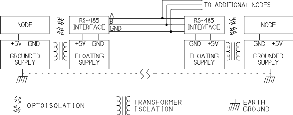
Complete isolation requires isolating the power supplies and the network's signals. The power supplies typically use transformer isolation, while the signals use optoisolators:

A one-chip way to achieve isolation is to use Maxim's MAX1480, which contains its own transformer-isolated supply and optoisolated signal path.
Auto-switching Link
One of challenges in designing an RS-485 link is controlling the driver-enable lines. Because all of the nodes share a data path, only one driver can be enabled at a time. Before transmitting, a driver must be sure that the previous driver has been disabled.
Many RS-485 networks use a command/response protocol, where one node sends commands, and the node being addressed returns a response.
The UART in the node being addressed detects the final Stop bit in the middle of the bit width, or slightly sooner or later if the sender's clock doesn't match exactly. A very fast node may be ready to send a reply within a few microseconds after detecting the Stop bit. To prevent the need for a delay before responding, the sending node's driver should be disabled as soon as possible after the leading edge of its final Stop bit.
In most systems, the transmitting driver is enabled on the leading edge of the Start bit and remains enabled for the entire transmission, then is disabled as soon as possible after the final Stop bit. In the delays between transmissions, biasing holds the line in an idle state.
There are various ways that the transmitting node can determine when a transmission has finished and it's safe to disable the driver. The node may read back what it sent, or it may use a hardware or software timer to estimate the time needed to transmit.
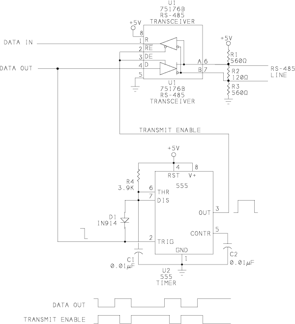
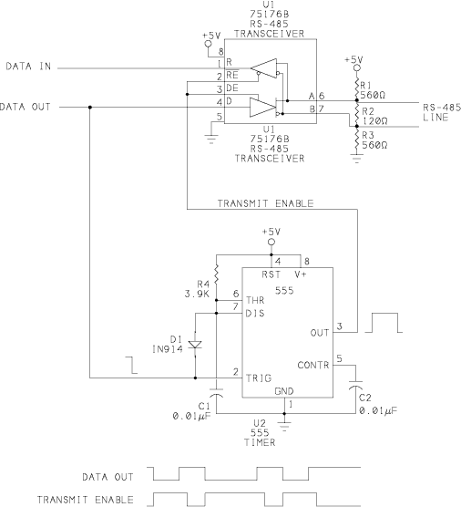
This circuit shows a completely automatic way to control the enable line so that the driver is disabled as quickly as possible, soon after the leading edge of the Stop bit:

With this circuit, the program code doesn't have to toggle a signal to enable and disable the driver, and a transmitting driver doesn't need to allow extra time to be sure that the previous driver has been disabled.
Unlike other methods of automatic control, there are no jumpers to set for a particular bit rate. I first learned of this method when I saw it in R.E. Smith's IRSFC24 Isolated RS-485 board.
Instead of keeping the transmitter enabled for the entire transmission, the circuit above enables the driver on the leading edge of the Start bit or any logic low at the driver's input, and it disables the driver about 40 microseconds after the leading edge of the Stop bit or any logic high at the driver's input. When the driver is disabled, biasing resistors ensure that the receiver's output is a logic high.
The delay is generated by a 555 timer configured as a monostable (one-shot). The enable inputs of the driver and receiver are tied together, so the receiver is disabled when the driver transmits.
The timer's output controls the transceiver's enable inputs. A falling edge at Data Out indicates a Start bit and triggers the timer. The timer's output goes high, enabling the driver and bringing line B more positive than line A. Diode feedback to the Trig input holds the timer's output high for as long as Trig remains low.
When Data Out goes high, the RS-485 line switches, bringing line A more positive than line B. The same logic high also causes the timer to begin timing out. About 40 microseconds after the rising edge, the timer's output goes low, disabling the driver. The delay ensures that the driver's RS-485 output switches without delay, while the driver is enabled. When the driver is disabled, the biasing components continue to hold A more positive than B.
In a similar way, any falling edges in the transmitted data enable the driver, and any rising edges disable the driver after the delay. On the final Stop bit, the driver is disabled no later than 40 microseconds after the Stop bit's leading edge.
At rates of 9600 bps or less, the bit width is greater than 100 microseconds, which means that the driver is disabled at around the middle of the bit width. At faster bit rates, the driver will still be disabled no more than 40 microseconds after the Stop bit's leading edge. For networks that need very fast response time at faster bit rates, decrease R4 for a shorter delay.
A downside to this circuit is that the final voltage for logic zeros is the biasing voltage, which is usually less than the differential voltage when the driver is enabled. But since the biasing voltage needs to be great enough to prevent errors due to noise on an idle line, it should do the job for active logic states as well.
